Next: Single Slit Diffraction Up: Diffraction Previous: Diffraction Contents
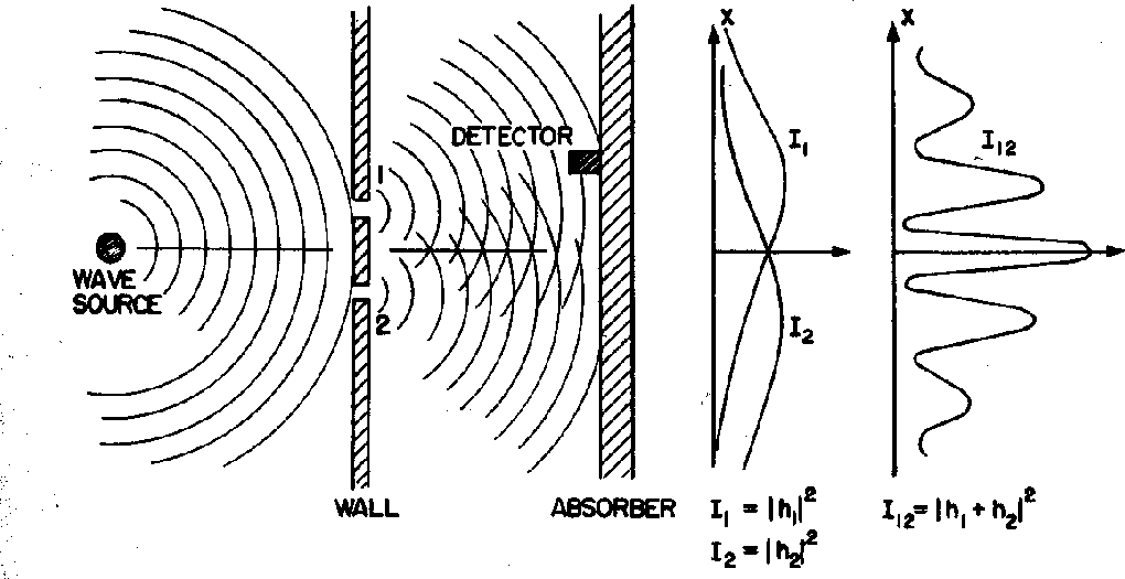
Water waves will exhibit a diffractive interference pattern in a 2 slit experiment
as diagrammed below.
The diagram shows the crests of the water waves at some time.
Downstream from the slits, we will see constructive interference where the waves from the
slits are in phase and destructive interference where they are 180 degrees out of phase,
for example where a crest from one slit meets a trough from the other.
The plot labeled
![]() shows the interference pattern at the location of the absorber.
Diffraction is a simple wave phenomenon.
shows the interference pattern at the location of the absorber.
Diffraction is a simple wave phenomenon.
The diffraction of light was a well known phenomenon by the end of the 19th century and was well explained in classical ElectroMagnetic theory since light was held to be a EM wave. The diffraction pattern from two narrow slits is particularly easy to understand in terms of waves. The setup is shown in the diagram below.
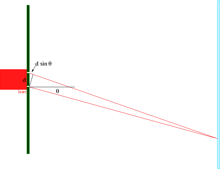
EM waves of wavelength
![]() are emitted from a single light-source, like a laser.
They travel to two narrow slits, (for simplicity) equidistant from the source, and a distance
are emitted from a single light-source, like a laser.
They travel to two narrow slits, (for simplicity) equidistant from the source, and a distance
![]() apart.
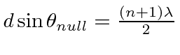
Light travels from the slits to a detection screen.
A diffraction pattern can be seen on the detection screen, like the one shown in the picture below.
apart.
Light travels from the slits to a detection screen.
A diffraction pattern can be seen on the detection screen, like the one shown in the picture below.
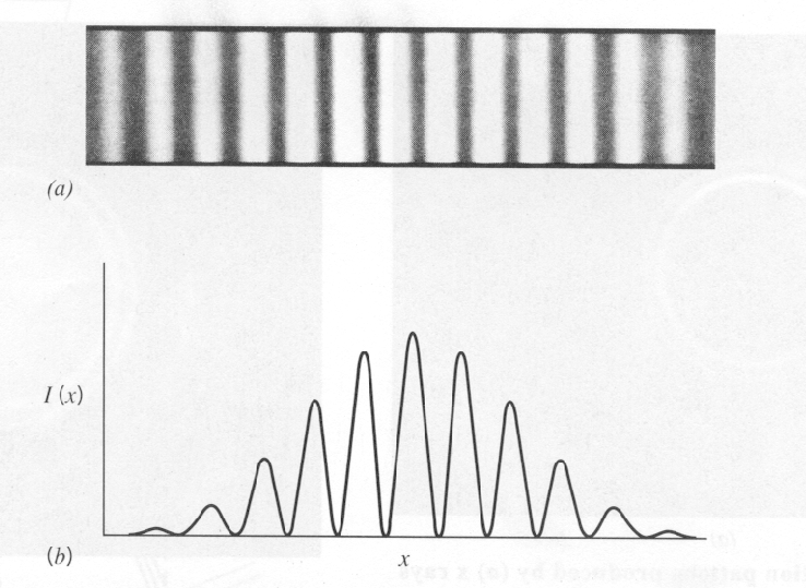
The center of the diffraction pattern occurs at the location on the screen equidistant from each slit where
the waves from the two slits are in phase (because they have traveled exactly the same distance)
and the fields add, so the waves interfere constructively and there is an intensity maximum.
Some distance off this center of the diffraction pattern, there will be destructive interference
between waves from the two slits and the intensity will be zero.
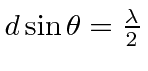
This will occur when the distance traveled by two waves differs by
 ,
so the waves are 180 degrees out of phase and the fields from the two slits cancel.
,
so the waves are 180 degrees out of phase and the fields from the two slits cancel.
We can compute this location by looking at the above diagram.
We assume that the distance to the screen is much greater than
![]() .
For light detected at an angle
.
For light detected at an angle
![]() , the extra distance traveled from slit 1 is just
, the extra distance traveled from slit 1 is just
![]() .
So the angle of the first minimum (or null) can be found from the equation
.
So the angle of the first minimum (or null) can be found from the equation
 .
.
More generally we will get a maximum if the paths from the slits differ by an integer number of wavelengths
![]() and we will get a null when the paths differ by a half integer number wavelengths.
and we will get a null when the paths differ by a half integer number wavelengths.
 .
.
Although it is very difficult because electrons are charged, 2 slit electron diffractionhas also been observed.
So, all kinds of particles seem to diffract indicating there is some kind of wave involved. We will now continue with some thought experiments on diffraction to illustrate the physics that Quantum Mechanics needed to match.
* Example:
Derive the location of the nodes in the diffraction pattern from two narrow slits a distance ![]() apart.
Now try to compute the intensity distribution.*
apart.
Now try to compute the intensity distribution.*
Jim Branson 2013-04-22